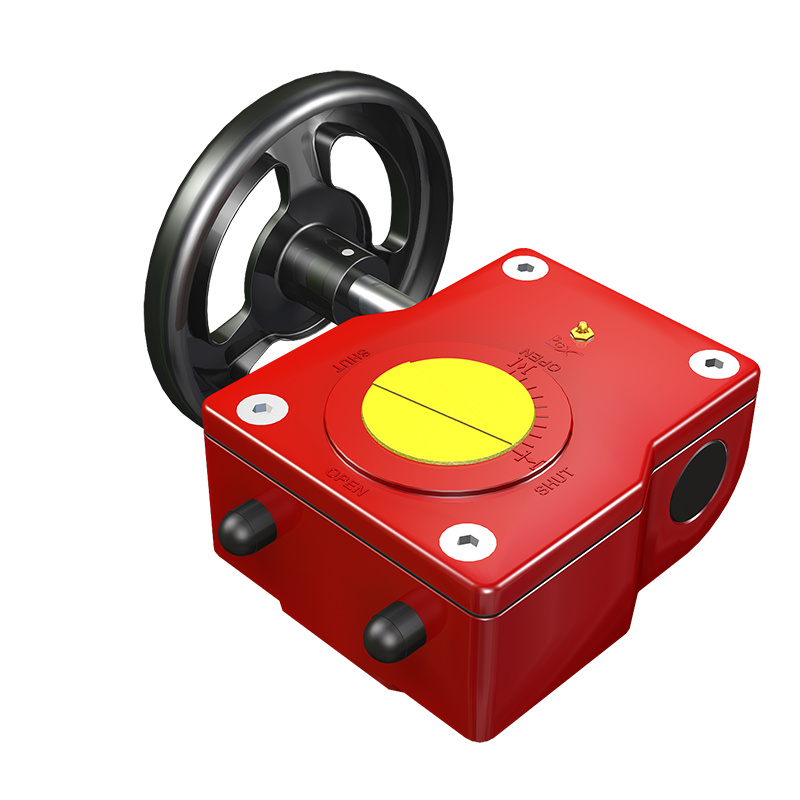
Aluminium Alloy Quarter-Turn Manual Gearbox
Connect the bottom flange of the gear operator to the upper flange of the valve and slide the valve shaft into the hole on the worm gear. Tighten the flange bolt. The valve can be closed by turning the hand-wheel clockwise and opened by turning the hand-wheel counterclockwise. On the upper face of the gear operator, a position indicator and a position marking are mounted, through which the position of switch can be directly observed. The gear operator is also equipped with a mechanical limit screw, which can be adjusted and function to limit the position at the switch extreme position.
▪ Lightweight aluminium die-cast alloy (ACD 12) casing
▪ IP65 graded protection
▪ Nickel-phosphorus plated input shaft
▪ NBR sealing materials
▪ Suitable for -20℃~120℃ working conditions
▪ Aluminum-bronze worm gear
▪ Stainless steel input shaft
Main Components List
|
Part name |
Material |
|
Cover |
Aluminum alloy |
|
Housing |
Aluminum alloy |
|
Worm gear/ Quadrant |
Ductile Iron |
|
Input shaft |
Protected Steel |
|
Position indicator |
Polyamide66 |
Main Technical Parameter
|
Model |
Gear ratio |
Rating input(Nm) |
Rating output(Nm) |
Hand-wheel |
|
SD-10 |
40:1 |
16.5 |
150 |
100 |
|
SD-15 |
37:1 |
25 |
250 |
150 |
|
SD-50 |
45:1 |
55 |
750 |
300 |
|
SD-120 |
40:1 |
100 |
1200 |
400 |
To ensure reliable gearbox operation, the maintenance instructions included in this manual must be observed.
1.After the commissioning is completed, it is recommended that to perform a test run every six months;
2.Check the gearbox operation record for this cycle to see if there is any abnormality record.
3.Check the gearbox for leaks.
4.Check the bolts of the gearbox to the flange on the valve.
5.Check all fastening bolts on the gearbox.
6.Check the accuracy of the gearbox position indicator and tightening of limit adjustment bolt (If the gearbox used in frequent vibration circumstance, it is recommended that checking the condition in shorter term)
