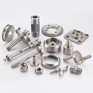
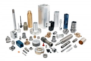
CNC machining service
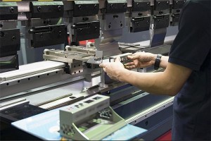
How Does CNC Machining Work?
The basic CNC machining process includes the following stages:
Designing the CAD model
Converting the CAD file to a CNC program
Preparing the CNC machine
Executing the machining operation
When a CNC system is activated, the desired cuts are programmed into the softwareand dictated to corresponding tools and machinery, which carry out the dimensional tasks as specified, much like a robot. In CNC programming, the code generator within the numerical system will often assume mechanisms are flawless, despite the possibility of errors, which is greater whenever a CNC machine is directed to cut in more than one direction simultaneously. The placement of a tool in a numerical control system is outlined by a series of inputs known as the part program.
With a numerical control machine, programs are inputted via punch cards. By contrast, the programs for CNC machines are fed to computers through small keyboards. CNC programming is retained in a computer’s memory. The code itself is written and edited by programmers. Therefore, CNC systems offer far more expansive computational capacity. Best of all, CNC systems are by no means static since newer prompts can be added to pre-existing programs through revised code.
Types of CNC Machining Operations CNC Turning
CNC Turning is a machining process which employs single-point cutting tools to remove material from the rotating workpiece. Operational capablities of the turning process include boring, facing, grooving, and thread cutting. In lathe machines, pieces are cut in a circular direction with indexable tools. With CNC technology, the cuts employed by lathes are carried out with precision and high velocity. CNC lathes are used to produce complex designs that wouldn’t be possible on manually run versions of the machine. Overall, the control functions of CNC-run mills and lathes are similar. As with CNC mills, lathes can be directed by G-code or unique proprietary code. However, most CNC lathes consist of two axes — X and Z.
CNC Milling
CNC Milling is a machining process which employs rotating multi-point cutting tools to remove material from workpiece. CNC mills are capable of running on programs comprise of number-and letter-based prompts that guide pieces acorss various distances. The programming employed for a mill machine could be based on either Gode or some unique language developed bring team, Basic m-cos consist of a three-axis system (X, Y and Z), though most newer mills can accommodate three additional axes. Operitional capabilities of the milling process include face milling-cutting shallow, flat surfaces and flat-bottomed cavitites into the workpiece-and peripheral milling-cutting deep cavities, such as slots and threads, into workpiece.
5 Axis machining
The 3, 4, or 5 axis machining is defined related to the number of directions in which the cutting tool can move, this also determines the ablility of a CNC machine to move a workpiece and a tool. 3-axis machining centers can move a component in X and Y directions and the tool moves up and down along Z- axis, while on the 5 axis machining center, the tool can move across the X, Y and Z linear axes as well as rotates on the A and B axes, which makes the cutter can approach the workpiece from any direction and any angle. 5 axis machining is different from 5-sided machining. Therefore, 5 axis CNC machining services allow iinfinte possibilities of the machined parts. Hook surface machining, unusual shape machining, hollow machining, punching, oblique cutting, and more special prcesses can be with 5 axis CNC machining service.
Swiss Type Machining
Swiss type machining is called for machining by Swiss type lathe or a Swiss automatic lathe, it is a modern precision manufacturing that can produce extremely small parts quickly and accurately.
A Swiss machine works by feeding bar stock through a guide bushing, which firmly supports the material as it feeds into the tooling area of the machine.
Compared with traidtional automatic lathes Swiss type lathes are uniquely capable of producing extremely small, precise parts at a rapid pace. The combination of high precision and high production volume make Swiss machines a critical piece of equipment for shops that must produce a large volume of small and intricate parts with little margin for error.
Material Used in CNC Machining Application
While there are a wide-range of materials you can use in a CNC machine, the most commonly employed materials used are:
Aluminum Alloys
● Al 6061-T6
● Al6063-T6
● Al7075-T6
● Al5052
● Al2024
Stainless steel Alloys:
● Stainless steel 303/304
● Stainless steel 316/316L
● Stainless steel 420
● Stainless steel 410
● Stainless steel 416
● Stainless steel 17-4H
● Stainless steel 18-8
Plastic:
● POM (Delrin),ABS (Acrylonitrile Butadiene Styrene)
● HDPE, Nylon(PA),PLA,PC (Polycarbonate)
● PEEK (Polyether Ether Ketone)
● PMMA (Polymethyl Methacrylate or Acrylic)
● PP (Polypropylene)
● PTFE (Polytetrafluoroethylene)
Copper & Brass Alloys:
● Copper 260
● Copper 360
● H90, H80, H68, H62
Carbon steel Alloys:
● Steel 1018, 1024, 1215
● Steel 4140, 4130
● Steel A36…
Titanium Alloys:
● Titanium (Grade 2)
● Titanium (Grade 5)
CNC Finishing and Post-processing Options
Surface finishing is the final step of CNC machining. Finishing can be used to remove aesthetic flaws, improve a product’s appearance, provide additional strength and resistance, adjust electrical conductivity, and much more.
● As Machined
● Anodizing (Type II & Type III)
● Powder coating
● Electroplating
● Bead blasting
● Tumbled
● Passivation
● Chemical Film(Chromate Conversion Coating)