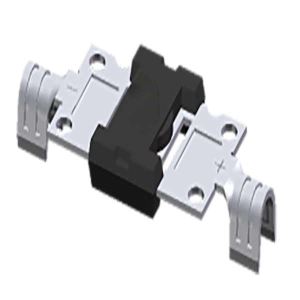
Photovoltaic Solar Cell Protection Schottky Rectifier YX-01
Typical Applications
For use in solar cell junction box as a bypass diode for protection.
Mechanical Data
Case: YX-01
Molding compound meets UL 94 V-0 flammability rating
UL 94 V-0
Terminals: Matte tin plated leads
Polarity: As marked on the body
Technical data
| MAXIMUM RATING (TA = 25 ℃ unless otherwise noted)(TA = 25 ℃, ) | |||||
| PARAMETER |
SYMBOL |
GF3045 |
GF4045 |
GF5045 |
UNIT |
| Maximum repetitive peak reverse voltage |
VRRM |
45 |
V |
||
| Maximum RMS voltage |
VRMS |
31.5 |
V |
||
| Maximum DC blocking voltage |
VDC |
45 |
V |
||
| Maximum average forward rectified current |
IF(AV) |
30.0 |
40.0 |
50.0 |
A |
| Peak forward surge cuurent 8.3ms single half sine_wave superimposed on rated load @ 60Hz, |
IFSM |
400 |
A |
||
| Operating junction temperature range |
TJ |
-55 to +200 |
℃ |
||
| Storge temperature range |
TSTG |
-55 to +200 |
℃ |
||
| ELECTRICAL CHARACTERISTICS (TA = 25 ℃ unless otherwise noted) (TA = 25 ℃, ) | ||||||
| PARAMETER |
TEST CONDITIONS |
SYMBOL |
GF3045 |
GF4045 |
GF5045 |
UNIT |
| Maximum instantaneous forward voltage | 30.0 A |
VF(1) |
0.6 |
- |
- |
V |
| 40.0 A | - | 0.6 |
- |
|||
| 50.0 A | - | - |
0.6 |
|||
| Maximum instantaneous reverse current at rated DC blocking voltage | TJ = 25 ℃ |
IR(1) |
0.5 |
mA |
||
| TJ = 125 ℃ |
100 |
|||||
Note
Pulse test: 300us pulse width, 1% duty cycle :300us,1%。
| THERMAL CHARACTERISTICS (TA = 25 ℃ unless otherwise noted) (TA = 25 ℃, ) | ||||||
| PARAMETER |
TEST CONDITIONS |
SYMBOL |
GF3045 |
GF4045 |
GF5045 |
UNIT |
| Typical thermal resistance | Junction to Case |
RthJ-C |
0.8 |
℃/W |
||
Application
Used for photovoltaic systems
Solution
● Installation or maintenance should be operated by the professional personnel.
● For protection against electric shock, while being assembled or disassembled, make sure connectors isolated from the power supply.
● Don’t connected or disconnected under load.
● During the assembly process, keep the connector away from any corrosive materials.
Attention
1.Gently holding and releasing in transportion, no damage to product.
2.When installing the junction box, making sure the solar panel is not working and you can’t touch the plus and minus rails at the same time avoiding an electronic shock and diode disruption.
3.Do not connect the plus and the minus together of the same junction box at any time.
4.Do not insert and withdrawal the plus and minus connector frequently except repairs ecause the sealing performance will be cut down.
6.When installation, evenly smear the silica adhesive on the base of the junction box in order to prevent leakage.
7.Keep the rubber clean and no adhesive when assembly, or it affect the efficiency of the panel.
8.Keep paraffin away from PV junction box and connector, such as, oil,ubricant,electric revival,and other paraffin substance
FAQ
