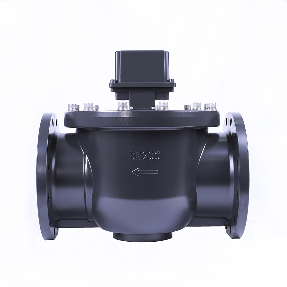
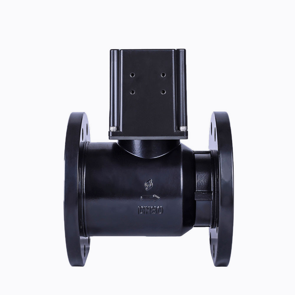
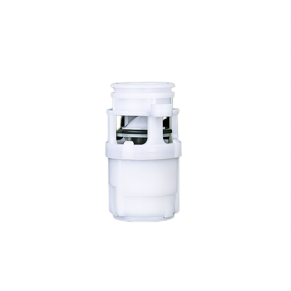
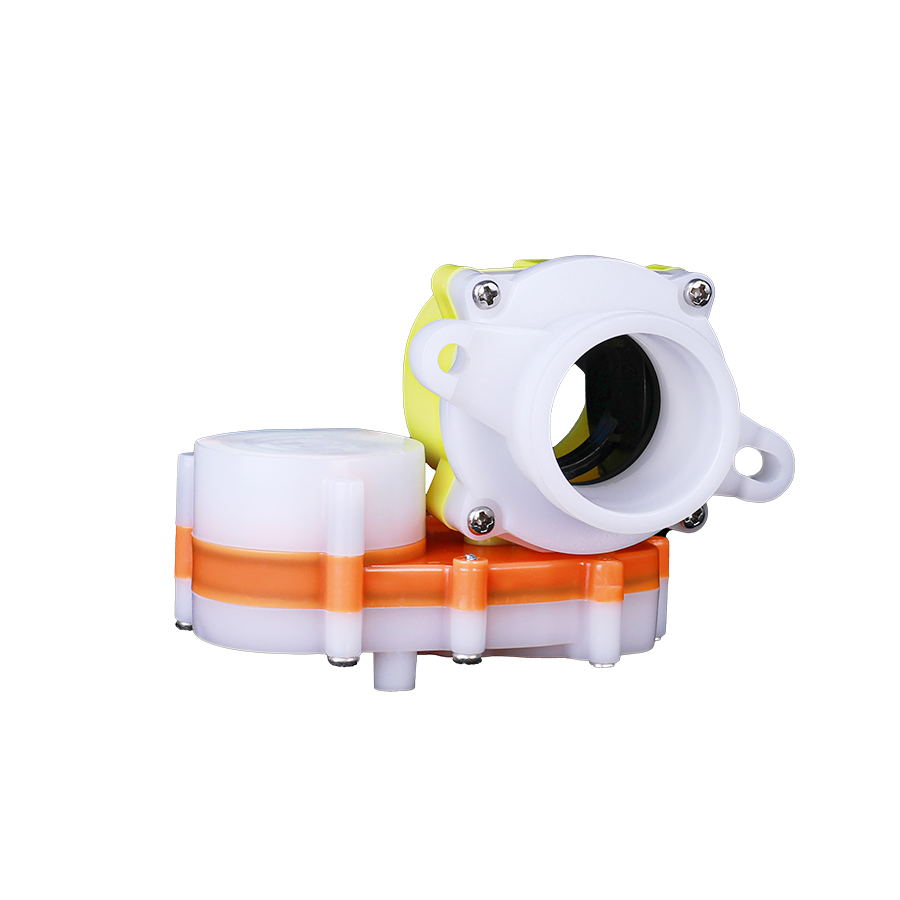
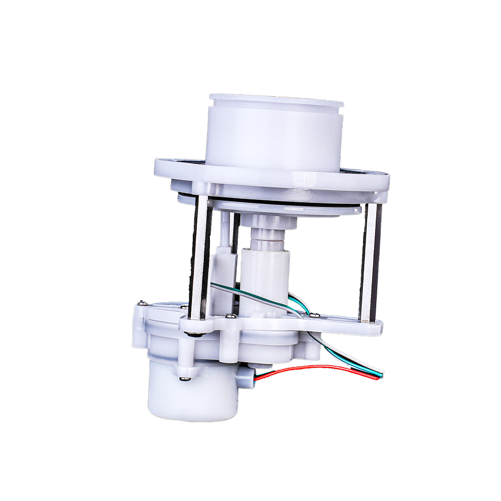
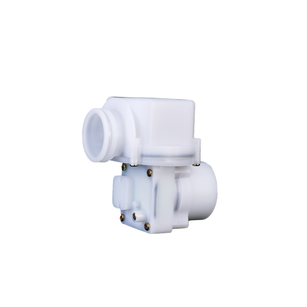
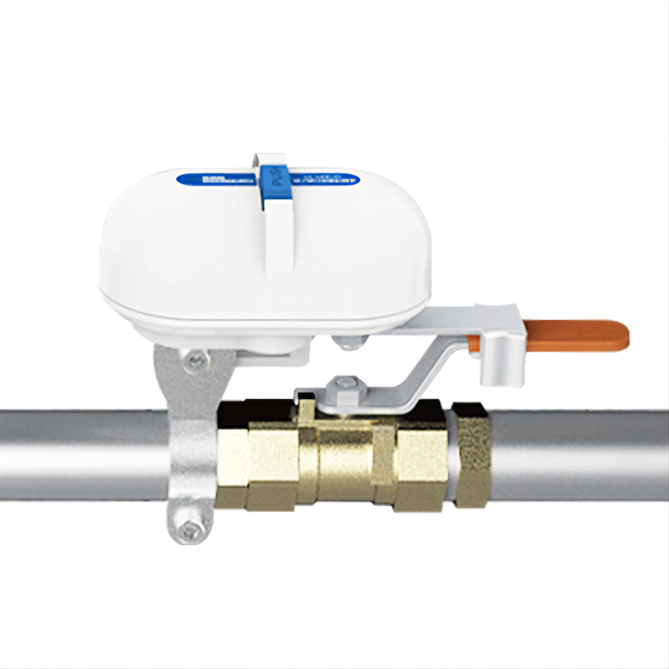
Pipeline Motor Ball Valve
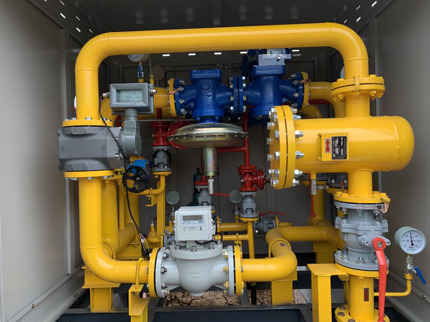
Installation location
The ball valve can be installed on the gas pipeline
Product Advantages:
Gas pipeline ball valve’s feature and advantages
1. It is a slow-opening and fast-closing valve, and the closing time is less than or equal to 2s;
2. No pressure loss during use;
3. Good sealing, stable and reliable performance.
4. Special internal and external track structure design, accurate positioning and reliable sealing; reduces the valve starting torque, and can realize valve opening in high pressure environment, low load and low power consumption;
5. The valve body is made of cast aluminum alloy, which is light in weight, good in corrosion resistance, and can withstand a nominal pressure of 1.6MPa; the overall structure is resistant to shock, vibration, high and low temperature, salt spray, etc., and can adapt to various complex outdoor environments.
6. The motor and gear box are designed to be fully sealed, with a protection level of ≥ IP65, and the motor and gear box have no contact with the transmission medium, and have good explosion-proof performance. Greatly improved valve reliability and service life;
7. The strength of the actuator is strong, and it can be blocked directly after opening and closing in place, or it can be brought to the position switch;
8. After the valve is opened and closed in place, the movement mechanism is automatically locked to ensure that the valve will not malfunction due to external force when it is in a stable state;
9. The micro-motor is finely processed, the commutator is gold-plated, and the brush is made of precious metal, which greatly improves the corrosion resistance and stability of the micro-motor itself, and ensures the long-term reliable operation of the motor valve;
10. The direction of air intake can be adjusted.
Instruction For Use
1. The valve should be installed horizontally, and the valve should be installed on the pipeline through standard flange bolt connection. Before installation, the iron slag, rust, dust and other sundries at the installation interface should be cleaned to prevent the gasket from being scratched and damaged causing leakage;
2. The transmission part of the valve can be turned 180° according to customer requirements, and it can be used normally after adjustment.
3. The red and black wires are the motor wires, the red wire is connected to the negative electrode, and the black wire is connected to the positive electrode to open the valve;
4. The valve can be equipped with open and close in-position signal output, and it is recommended to use the switch signal; the white line is the open in-position signal feedback line, which is short-circuited when the open is in place, and the rest of the stroke is open; the blue line is the closed-in position feedback signal line, which is short-circuited when it is closed in place. , the rest of the trip is open circuit;
5. The valve should be in the closed state before installation, it is strictly forbidden to use it under the condition of overpressure or air leakage, and it is strictly forbidden to detect leakage with open fire;
6. The appearance of this product has a nameplate.
Tech Specs
|
No.号 |
Itrms |
Requirement |
|||||||
|
1 |
Working medium |
Nature gas LPG |
|||||||
|
2 |
Nominal diameter(mm) |
DN25 |
DN32 |
DN40 |
DN50 |
DN80 |
DN100 |
DN150 |
DN200 |
|
3 |
Pressure range |
0~0.8Mpa |
|||||||
|
4 |
Nominal pressure |
1.6MPa |
|||||||
|
5 |
Operating Voltage |
DC3~7.2V |
|||||||
|
6 |
Operating current |
≤70mA(DC4.5V) |
|||||||
|
7 |
Max current |
≤220mA(DC4.5V) |
|||||||
|
8 |
Blocked current |
≤220mA(DC4.5V) |
|||||||
|
9 |
Operating temperature |
-30℃~70℃ |
|||||||
|
10 |
Storage temperature |
-30℃~70℃ |
|||||||
|
11 |
Operating humidity |
5%~95% |
|||||||
|
12 |
Storage humidity |
≤95% |
|||||||
|
13 |
ATEX |
ExibⅡB T4 Gb |
|||||||
|
14 |
Protection class |
IP65 |
|||||||
|
15 |
Opening time |
≤250s(DC4.5V/0.8MPa) (DN25~DN50) |
≤450s (DC4.5V/0.8MPa) (DN80~DN200) |
||||||
|
16 |
Closing time |
≤2s(DC4.5V) |
|||||||
|
17 |
Leakage |
Under 0.8MPa, leakage ≤0.55dm3/h(compress time 2min) |
|||||||
|
Under 5KPa, leakage≤0.1dm3/h(compress time2min) |
|||||||||
|
18 |
Motor risistance |
21Ω±1.5Ω |
|||||||
|
19 |
switch contact resistance |
≤1.5Ω |
|||||||
|
20 |
Endurance |
≥6000 times(or 10 years) |
|||||||
Structure Specs
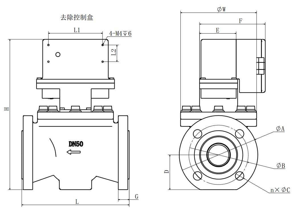
| DiameterDem(mm) |
GDF-1-DN25 |
GDF-1-DN32 |
GDF-1-DN40 |
GDF-1-DN50 |
GDF-1-DN80 |
GDF-1-DN100 |
GDF-1-DN150 |
GDF-1-DN200 |
|
L |
160 |
180 |
226 |
226 |
310 |
350 |
480 |
520 |
|
W |
130 |
130 |
160 |
160 |
220 |
246 |
336 |
412 |
|
H |
293 |
295 |
316 |
316 |
355 |
380 |
431 |
489 |
|
A |
115 |
140 |
150 |
165 |
200 |
220 |
285 |
340 |
|
B |
85 |
100 |
110 |
125 |
160 |
180 |
240 |
295 |
|
C |
14 |
18 |
18 |
18 |
18 |
18 |
22 |
22 |
|
D |
59 |
59 |
73 |
73 |
92 |
106 |
132 |
165 |
|
E |
77 |
77 |
77 |
77 |
77 |
77 |
77 |
77 |
|
F |
138.5 |
138.5 |
138.5 |
138.5 |
138.5 |
138.5 |
138.5 |
138.5 |
|
G |
18 |
18 |
23 |
23 |
23 |
23 |
25 |
28 |
|
L1 |
114 |
114 |
114 |
114 |
114 |
114 |
114 |
114 |
|
L2 |
35 |
35 |
35 |
35 |
35 |
35 |
35 |
35 |
|
n |
4 |
4 |
4 |
4 |
8 |
8 |
8 |
12 |
