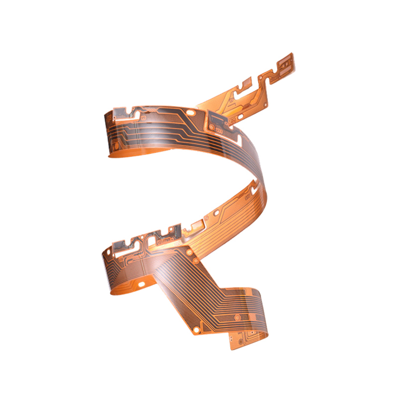
Rigid Flex Printed Circuit Boards
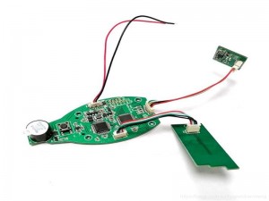
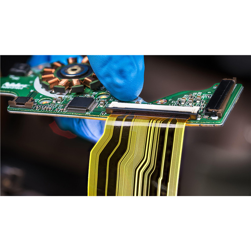
product application
Common applications of rigid flexible combination PCB and semi flexible PCB design
Medical imaging instruments
.section-block-demo39-advantage1 { position: relative; padding: 3.5rem 0; } .section-block-demo39-advantage1 .advantage-items { padding: 2rem 0; display: flex; flex-wrap: wrap; } .section-block-demo39-advantage1 .advantage-item { position: relative; padding: 10px; } .section-block-demo39-advantage1 .item-order { position: absolute; top: 2.2rem; right: 2.5rem; font-size: 5.3rem; font-weight: 700; line-height: 1; color: #ffffff; opacity: 0; letter-spacing: 2px; text-shadow: var(–bs-theme-color) 1px 0 0, var(–bs-theme-color) 0 1px 0, var(–bs-theme-color) -1px 0 0, var(–bs-theme-color) 0 -1px 0; } .section-block-demo39-advantage1 .item-inner:hover .item-order { opacity: 1; } .section-block-demo39-advantage1 .item-inner { position: relative; display: block; width: 100%; height: 100%; padding: 2.7rem; background-color: #f7f9ff; border: 1px solid var(–bs-sec-theme-color); z-index: 1; } .section-block-demo39-advantage1 .item-inner::after { content: ”; width: 100%; height: 100%; position: absolute; top: 0; left: 0; z-index: -1; pointer-events: none; background-color: #ffffff; } .section-block-demo39-advantage1 .item-inner:hover { border-color: transparent; } .section-block-demo39-advantage1 .item-inner:hover::after { opacity: 0; } .section-block-demo39-advantage1 .item-inner .item-ico { height: 58px; } .section-block-demo39-advantage1 .item-inner .item-info { padding-top: 2rem; } .section-block-demo39-advantage1 .item-inner .item-title { margin: 0 0 1rem; font-size: 2.5rem; font-weight: 700; } .section-block-demo39-advantage1 .item-inner .item-desc { font-size: 1.28rem; line-height: 1.33; color: #65605f; } .section-block-demo39-advantage1 .item-inner, .section-block-demo39-advantage1 .item-order { -webkit-transition: all .4s ease; transition: all .4s ease; } @media only screen and (max-width:1280px) { .section-block-demo39-advantage1 .item-order { font-size: 4.2rem; } .section-block-demo39-advantage1 .item-inner .item-title { font-size: 2rem; } } @media only screen and (max-width:992px) { .section-block-demo39-advantage1 .item-inner { padding: 1.5rem; } .section-block-demo39-advantage1 .item-order { top: 1.2rem; right: 1.5rem; } .section-block-demo39-advantage1 .advantage-item { padding: 5px; } } @media only screen and (max-width:768px) { .section-block-demo39-advantage1 .item-inner { padding: 1.2rem; } .section-block-demo39-advantage1 .item-inner .item-title { font-size: 1.5rem; } .section-block-demo39-advantage1 .item-inner .item-desc { font-size: 1.1rem; } } @media only screen and (max-width:576px) { .section-block-demo39-advantage1 { padding: 1rem 0; } .section-block-demo39-advantage1 .item-order { font-size: 3.5rem; } }
Automotive Applications
Aviation
Wearable devices
Smartphones and laptops
Sporting facilities
Bottom line
.section-block-demo39-advantage1 { position: relative; padding: 3.5rem 0; } .section-block-demo39-advantage1 .advantage-items { padding: 2rem 0; display: flex; flex-wrap: wrap; } .section-block-demo39-advantage1 .advantage-item { position: relative; padding: 10px; } .section-block-demo39-advantage1 .item-order { position: absolute; top: 2.2rem; right: 2.5rem; font-size: 5.3rem; font-weight: 700; line-height: 1; color: #ffffff; opacity: 0; letter-spacing: 2px; text-shadow: var(–bs-theme-color) 1px 0 0, var(–bs-theme-color) 0 1px 0, var(–bs-theme-color) -1px 0 0, var(–bs-theme-color) 0 -1px 0; } .section-block-demo39-advantage1 .item-inner:hover .item-order { opacity: 1; } .section-block-demo39-advantage1 .item-inner { position: relative; display: block; width: 100%; height: 100%; padding: 2.7rem; background-color: #f7f9ff; border: 1px solid var(–bs-sec-theme-color); z-index: 1; } .section-block-demo39-advantage1 .item-inner::after { content: ”; width: 100%; height: 100%; position: absolute; top: 0; left: 0; z-index: -1; pointer-events: none; background-color: #ffffff; } .section-block-demo39-advantage1 .item-inner:hover { border-color: transparent; } .section-block-demo39-advantage1 .item-inner:hover::after { opacity: 0; } .section-block-demo39-advantage1 .item-inner .item-ico { height: 58px; } .section-block-demo39-advantage1 .item-inner .item-info { padding-top: 2rem; } .section-block-demo39-advantage1 .item-inner .item-title { margin: 0 0 1rem; font-size: 2.5rem; font-weight: 700; } .section-block-demo39-advantage1 .item-inner .item-desc { font-size: 1.28rem; line-height: 1.33; color: #65605f; } .section-block-demo39-advantage1 .item-inner, .section-block-demo39-advantage1 .item-order { -webkit-transition: all .4s ease; transition: all .4s ease; } @media only screen and (max-width:1280px) { .section-block-demo39-advantage1 .item-order { font-size: 4.2rem; } .section-block-demo39-advantage1 .item-inner .item-title { font-size: 2rem; } } @media only screen and (max-width:992px) { .section-block-demo39-advantage1 .item-inner { padding: 1.5rem; } .section-block-demo39-advantage1 .item-order { top: 1.2rem; right: 1.5rem; } .section-block-demo39-advantage1 .advantage-item { padding: 5px; } } @media only screen and (max-width:768px) { .section-block-demo39-advantage1 .item-inner { padding: 1.2rem; } .section-block-demo39-advantage1 .item-inner .item-title { font-size: 1.5rem; } .section-block-demo39-advantage1 .item-inner .item-desc { font-size: 1.1rem; } } @media only screen and (max-width:576px) { .section-block-demo39-advantage1 { padding: 1rem 0; } .section-block-demo39-advantage1 .item-order { font-size: 3.5rem; } }
| Feature | AREX´s technical specification |
| Number of layers | 1 – 12 layers, with 1 – 2 conductive layers in bending area. |
| Technology highlights | The process uses controlled depth routing of the FR-4 to achieve a flexible / bending section within a traditionally rigid FR-4. Only suitable for static operations – bends typically just for installation. A lower cost solution for some very specific “flex-to-fit”applications. |
| Bending performance | 50 x bend cycles of 0° – 90° – 0° |
| Bend features | 5mm radius / max bending angle 90° |
| Materials | Specialized FR-4 for static flex applications |
| Copper weights (finished) | 35μm |
| Minimum track and gap | 0.075mm / 0.075mm |
| PCB thickness | 1.00mm – 2.00mm |
| PCB thickness in flex section | 0.25mm ± 0.05mm |
| Maxmimum dimensions | 538mm x 610mm |
| Surface finishes available | HASL (SnPb), LF HASL (SnNiCu), OSP, ENIG, Immersion tin, Immersion silver, Electrolytic gold, Gold fingers |
| Minimum mechanical drill | 0.20mm |
| Minimum laser drill | 0.10mm standard, 0.075mm advanced |
.section-block-demo1-productDetail1 .tab-nav { border-bottom: 1px solid #eee } .section-block-demo1-productDetail1 .nav-item { font-size: 1.4rem; border: 1px solid #eee; border-bottom: none; border-radius: 5px 5px 0 0; margin: 0 10px 0 0; padding: .5rem 1rem; } .section-block-demo1-productDetail1 .nav-item.active { background-color: var(–bs-theme-color); color: #fff; } .section-block-demo1-productDetail1 .tab-pannel-wrap { padding: 2rem 0; }